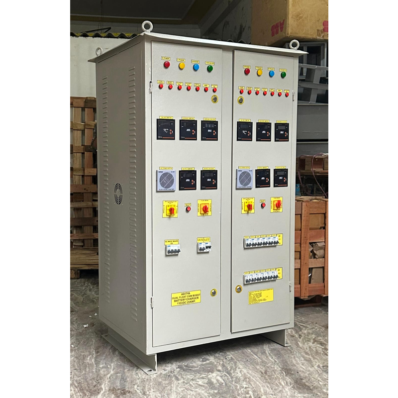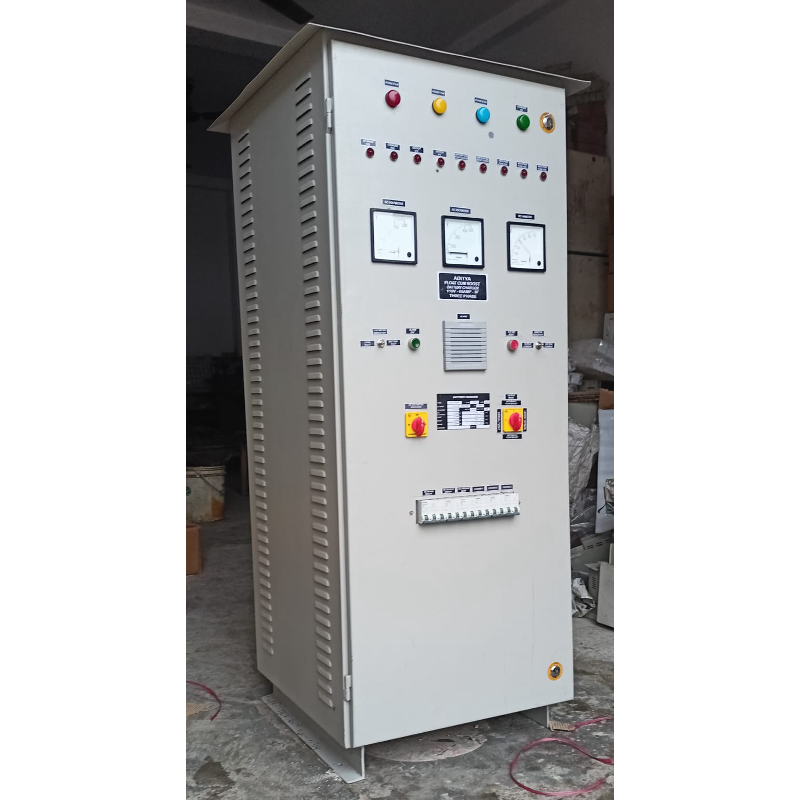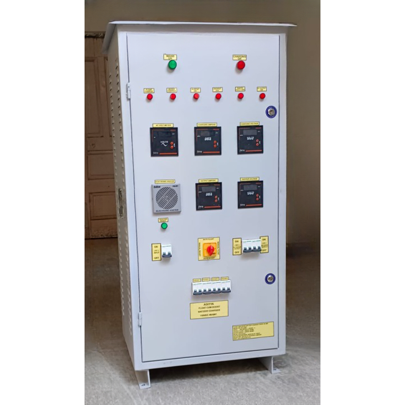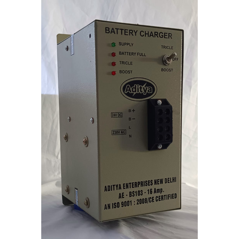
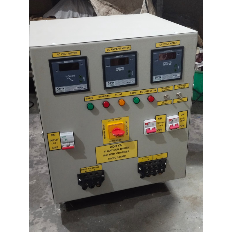
An FCBC Battery Charger, also known as a Float Cum Boost Charger, is an advanced battery charging system designed to efficiently maintain and charge batteries in both standby and load-sharing conditions. It operates in two modes: Float mode and Boost mode, ensuring the battery remains fully charged and ready for use without the risk of overcharging. In Float mode, the charger provides a constant voltage that is slightly lower than the battery’s full charge voltage. This keeps the battery charged continuously and compensates for self-discharge while also supplying power to the connected load. When the battery voltage drops below a preset level—such as after a heavy discharge—the charger automatically switches to Boost mode. In this mode, it delivers a higher voltage and current to quickly restore the battery’s capacity. Once the battery reaches the required voltage level, the system automatically stops boost charging and returns to Float mode, ensuring safety and prolonging battery life. It is commonly used in telecommunication systems, substations, power plants, control panels, and industrial automation setups where continuous DC power supply and reliable battery backup are essential. ---Technical Specs. 1. AC Input : a) Input Voltage : 170-260Vac 1Phase or 415Vac 3Phase b) Frequency : 50Hz 2. DC Output : a) Volt/cell : Float Charge 2.25V(VRLA) Boost Charge 2.30V(VRLA) b) Output Voltage : 24V/36V/48Vdc are available c) Current Rating : 20A/25A/30A/40A/50Amp are available 3. Cooling Arrangement : 1No. Fan Provided 4. Performance : a) Regulation for 0-100% rated load : +/- 1%. b) Ripple content in DC output : With Battery % : <1% pp Without Battery % : <1% pp c) Guaranteed efficiency : > 80% at rated output and nominal input d) Power Factor % : > 0.8 lag at rated output and nominal input. 5. Design Ambient : 0-50 degree Celsius 6. Mounting : Floor Mounting and Free Standing 2 Nos. Channel at Base. 7. Location : Indoor 8. Atmosphere : Hot & Dry 9. Cabinet a) Paint Type : Powder-coated paint b) Thickness of Sheet Steel : 1.6mm 10. Size of the unit : 500 x 460 x 360 mm (H x W x D) the size may vary if the customer requests customization. 11. For 1Phase FCBC, Indication : a) Main On b) Charger On c) Float Mode d) Boost Mode e) DC Output On 12. For 3Phase FCBC, Indication : a) R-Phase On b) Y-Phase On c) B-Phase On d) Charger On e) Float Mode f) Boost Mode g) DC Output On 13. Metering : a) Type : Digital or Analog